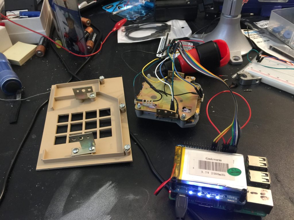
So, if I’m going to have 3 working phones for the Maker faire, I better get to building them. Today’s project is to get the keypad working. Oringally this keypad used a touch-tone signaling mechanism, but that wasn’t necessary for my purposes, so I just cut out all the DTMF hardware to get at the switches that the buttons operate. There are 12 buttons (3 columns and 4 rows) of numbers and symbols. The way these keypads operate is that each row and column has it’s own switch, and each button closes the switch for that column and that row. I wired each of those switches up to an I/O line on the raspberry pi 3B that I’m using as the brains of the Gruebox 1.
In the original phone, each column and row had its own tone, and so each number/symbol played two tones, hence Dual Tone Multi-Frequency. I just built a lookup table of switch values that map to symbols/numbers, and that’s how I decode which button is pressed.
Here’s a test run of the decoding:
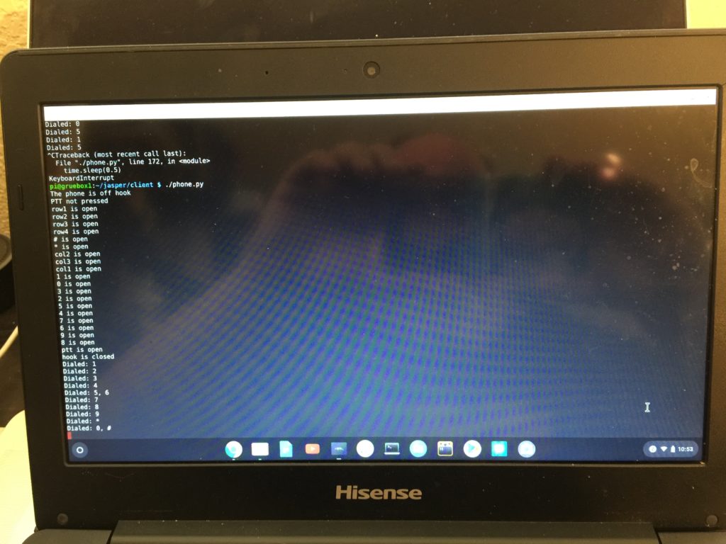
So all 12 buttons work. There is also a switch for the on/off hook that isn’t connected yet, so I’m just wired of off-hook for now, so I can test.
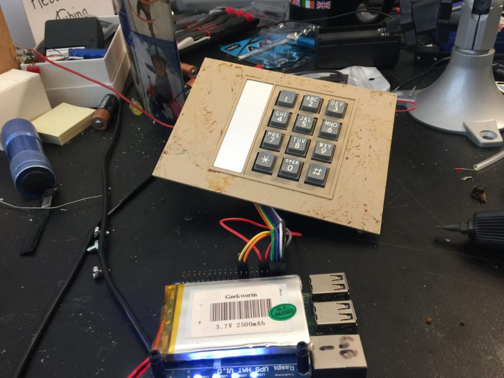
I also removed the fake wood-grain sticker on the faceplate. It’s still got some residue from the adhesive, but I’ll take care of that later. Assembled it looks like: